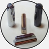
I smashed my synth and cracked the circuit board. There are 6 (now broken) traces crossing the crack. Each is about 1mm wide, with about 0.3mm between traces.
What is the best way to repair the broken traces?
I found some things on the internet for repairing traces, such as this
" Micro Tip Conductive Pen(CW2200MTP) Quickly creates conductive silver traces on most surfaces " http://www.circuitspecialists.com/prod.itml/icOid/824
or this "Circuit Trace Pen -- Makes instant conductive silver traces. Just draw a line from point-to-point, and in moments you have a highly conductive silver trace (as narrow as 1/16"). You can use it on printed circuit boards to link components, repair traces, " http://www.contacteast.com/product/prodpage.cfm?grp=4088BDCD-EEE0-11D4-8A710050DA5FEB55
Is it really this easy? Should I just drive over to Radio Shack or Electronic City and get this stuff?
I think the repair has to be flexible, because the circuit board is still cracked there, and it is right under a momentary switch that I hope to use again.
Circuit board trace repair
Moderator: Dave Mudgett
-
Earnest Bovine

- Posts: 8371
- Joined: 4 Aug 1998 11:00 pm
- Location: Los Angeles CA USA
- State/Province: -
- Country: United States
-
Jon Light (deceased)
- Posts: 14336
- Joined: 4 Aug 1998 11:00 pm
- Location: Saugerties, NY
- State/Province: -
- Country: United States
It's tricky to avoid any spill-over of solder onto adjacent paths but in the past I've stripped some fine gauge braided wire and soldered it across the break--basically a jumper cable. You are correct in assuming that the existent crack in your board is going to continually break any kind of repair that lacks a solid core such as wire. Maybe somebody can give you tips to avoid solder spill-over.
-
Earnest Bovine
- Posts: 8371
- Joined: 4 Aug 1998 11:00 pm
- Location: Los Angeles CA USA
- State/Province: -
- Country: United States
-
Jon Light (deceased)
- Posts: 14336
- Joined: 4 Aug 1998 11:00 pm
- Location: Saugerties, NY
- State/Province: -
- Country: United States
Yeah---poor-to-fair here too. Maybe try to lay in a strand of wire (pulled from some braided wire) while this paint/ink/ whatever is still wet. Something to give the joint some physical integrity. I really fear for your repair otherwise. This stuff you're talking about is real unlikely to have the plasticity to withstand any kind of flexing.
-
Bob Metzger
- Posts: 580
- Joined: 6 Jan 2000 1:01 am
- Location: Waltham (Boston), MA, USA
- State/Province: -
- Country: United States
-
Joey Ace

- Posts: 9791
- Joined: 11 Feb 2001 1:01 am
- Location: Hamilton, Ontario, Canada
- State/Province: -
- Country: United States
Repairing broken traces on a circuit board is not that difficult for an experienced tech.
That is, if it is not a multi-layer board.
The basic technique is to solder jumpers to correct the broken traces.
If you don't have the skills you can ruin the board, probably by lifting traces with excessive heat.
If you want to try, get a scrap circuit board and practice first. Use an iron of 60 watts or less.
If you're not sure of your skills, take it to any electronics repair shop. The tech does not have to understand Synths to repair a cracked board. If there's more wrong then you need the Synth guy.
-
ajm
- Posts: 1750
- Joined: 13 Nov 1999 1:01 am
- Location: Los Angeles
- State/Province: -
- Country: United States
I'd go with the bridge the gap with a wire approach. If the traces are not teeny-tiny you should be able to find someone that can do it. I'd also not get too carried away with the scraping.
I can believe the 1mm wide traces, but only 0.3mm between traces? Do you really mean 3.0mm between traces? If so, this should be an easy job.
Two things to be aware of:
1) Are there traces on both sides? If so, you'll need to fix both sides. Not a lot of extra work, providing you can easily get to both sides.
2)Is it a multi layer board with traces in the middle layers as well as the top and bottom? I've seen boards with up to 24 layers, but not in anything related to music. If it does have multiple layers, you may be in big trouble.
Keep us posted.
------------------
Artie McEwan
-
Earnest Bovine
- Posts: 8371
- Joined: 4 Aug 1998 11:00 pm
- Location: Los Angeles CA USA
- State/Province: -
- Country: United States
Thanks to all for the advice, much of which I will not take.
<BLOCKQUOTE><font size="1" face="Verdana, Arial, Helvetica">quote:</font><HR><SMALL>If you don't have the skills you can ruin the board, probably by lifting traces with excessive heat.
If you want to try, get a scrap circuit board and practice first. Use an iron of 60 watts or less. </SMALL><HR></BLOCKQUOTE>I can wreck a board with a 25-watt iron.
It's single-layer, single side. I got the board back in the synth now, there are no parts left over, and the synth works, except for the two pushbutton switches right over the crack. I don't feel like spending money for a pro repair because the broken buttons are just '1' and '2' on the numeric keypad, and shortcuts to sound categories and expansion cards, which I can live without as long as I have time to spin the big data entry wheel.
<BLOCKQUOTE><font size="1" face="Verdana, Arial, Helvetica">quote:</font><HR><SMALL>If you don't have the skills you can ruin the board, probably by lifting traces with excessive heat.
If you want to try, get a scrap circuit board and practice first. Use an iron of 60 watts or less. </SMALL><HR></BLOCKQUOTE>I can wreck a board with a 25-watt iron.
No, the gap is much thinner than the trace. A couple of them are really close. That's why I don't think I can keep the solder from shorting to the adjacent trace.<SMALL>I can believe the 1mm wide traces, but only 0.3mm between traces? Do you really mean 3.0mm between traces? If so, this should be an easy job.</SMALL>
It's single-layer, single side. I got the board back in the synth now, there are no parts left over, and the synth works, except for the two pushbutton switches right over the crack. I don't feel like spending money for a pro repair because the broken buttons are just '1' and '2' on the numeric keypad, and shortcuts to sound categories and expansion cards, which I can live without as long as I have time to spin the big data entry wheel.
-
Ole Dantoft
- Posts: 413
- Joined: 31 May 2001 12:01 am
- Location: Copenhagen, Denmark
- State/Province: -
- Country: United States
Earnest,
I'm glad to hear you have it working, or almost working at least.
I have done this sort of repair hundreds of times and it really isn't as hard as it may seem. It IS just a question of a piece of wire, a high-quality, temperature-controlled soldering iron with a VERY fine tip and most of all : A steady hand ! I work under a magnifying glass when doing these repairs but that's not strictly necessary. Should you need any assistance, just mail/call me !
Had I been closer to you, you could have sent me that board and I'd fix it for free ! (You can still send it to me and I'll still fix it for free, but that's probably not very tempting !)
Ole
-
Rich Paton
- Posts: 708
- Joined: 3 Dec 1999 1:01 am
- Location: Santa Maria, CA.,
- State/Province: -
- Country: United States
For the conductors used to "bridge" a broken board trace, I like to use "solder wick" desoldering braid on any repair where the trace width is wide enough. For smaller conductors,#30 AWG "wire wrap" wire.
~Most~ damage done to traces & boards during soldering operations is due to excessive time of the iron being applied, due to insufficient tip mass and/or too low a temp. setting. To play it safe, a more or less standard rule of thumb for max. iron contact with boards / traces / pads is about 3 sec., in any case.
Liquid rosin fluxes can be slightly diluted with 99% isopropyl alcohol, which will help avoid damage because the alcohol will radpidly evaporate when heated, which removes a suprisingly large amount of heat from the board area being heated. Use of a good liquid rosin flux such as Kester brand will also help reduce the time needed for heating, since its ability to remove oxidation from conductor and parts leads allows the production of a good solder joint much faster than is possible on surfaces with oxidation present (which means ALL surfaces, really). This is of course in addition to the cleaning of surfaces to be soldered prior to any tinning and actual soldering. Usually I use (carefully on boards) some "Scotchbright" for this. Be sure to remove all "Scotchbright" & removed contamination residue before fluxing & soldering!
And, good luck!
-
Michael Johnstone

- Posts: 3863
- Joined: 29 Oct 1998 1:01 am
- Location: Sylmar,Ca. USA
- State/Province: -
- Country: United States
-
Joey Ace
- Posts: 9791
- Joined: 11 Feb 2001 1:01 am
- Location: Hamilton, Ontario, Canada
- State/Province: -
- Country: United States
-
Michael Brebes
- Posts: 1281
- Joined: 4 Aug 1998 11:00 pm
- Location: Northridge CA
- State/Province: -
- Country: United States
Usually there are only two options.
1. Use an exacto knife to scrape down to bare copper on the traces and solder a piede of buss wire or a cut cap/resistor lead across the brake.
2. If there isn't enough space, follow the trace until you find the ends of the trace. Solder a wire between the two ends. It is usually easy to solder a wire onto the ends as there are usually electrical components there. You might need to cut off any exposed trace at the brake that might touch something else.
If you need any help, email me. I'm in Northridge.